Aluminium-copper cord end terminals, HMA type
Marcin Lis, Head of the ZAE ERGOM Laboratory
Daniel Mirowski, Head of the ZAE ERGOM Product Development Department
Michał Uciński, Product Engineer at ZAE ERGOM
Paweł Animucki, Product Engineer at ZAE ERGOM
Summary
HMA - aluminium-copper cord end terminals enable the connection of cables with aluminium conductors to terminals made of copper or its alloys. HMA cord end terminals perform all the functions of standard insulated cord end terminals (H...ERHN type) compliant with DIN 46228/1. They hold the wires that make up the conductor, reducing the risk of short circuits, protect against cutting the wires, increase the resistance of the connection to vibrations and shocks, and improve the reliability of the wire's attachment to the terminal.
Introduction
Cord end terminals, commonly available on the market and used by installers, made of thin-walled copper tubing, can only be used on cables with flexible copper wires. If such a terminal is mounted on an aluminium wire, electrochemical corrosion may occur at the contact surface. The same case may occur when an aluminium wire is directly mounted in a clamp made of another material, e.g. copper or its alloys.
In order to meet market needs, ERGOM has developed a new type of thin-walled cord end terminal that allows the connection of class 5 or 6 multi-wire aluminium conductors to screw or spring clamps. Both types of clamps are mainly found in low-voltage equipment, e.g. distribution blocks, Single-circuit or multi-circuit connectors, circuit breakers, while screw clamps are used in industrial extension cord plugs and sockets.
Cord end terminals made of rolled bimetal sheet metal in the form of a tube are available on the market. However, this tube is not completely closed and has loose longitudinal edges, which means that the connection is not completely tight, and the terminal is therefore exposed to electrolytic corrosion., Fig. 1.
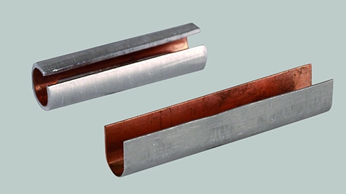
Fig. 1. Example of a bimetal tip in the form of an open tube.
Due to the aluminium wire is not completely insulated from the cord end terminal made of a different material, e.g. copper or its alloys, the electrical connection will gradually deteriorate. This case is particularly dangerous if such a connection is used in an environment with high humidity, where materials with different electrochemical potentials are placed together and current flows through the connection.
In order to eliminate the above-mentioned disadvantages of commercially available terminals, an alternative design of a bimetallic cord end terminal with increased resistance to electrochemical corrosion has been developed. This kind of terminal is closed longitudinally and has a bottom at the end, which completely eliminates points of direct contact between materials with different electrochemical potentials., Fig. 2.
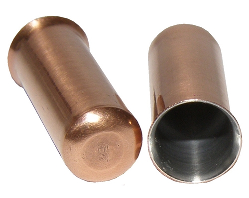
Fig. 2. Closed bimetal sleeve tip.
In addition, the same crimping tools that are currently used to crimp uninsulated and insulated cord end terminals (H...ERHN and HI...ERHL type) can be used to crimp the cable end connectors. Thanks to this solution, users adding a new type of connector in their applications do not need to build a new tool base.
HMA type sleeve terminal design
Aluminium-copper cord end terminals, HMA type meet all the functions of standard H...ERHN type copper cord end terminals manufactured in accordance with DIN 46228/1.
The basic function of this type of terminal is to secure the copper wires that make up the cable core in order to facilitate its installation in a screw or spring clamp. The use of a cord end terminal additionally reduces the risk of short circuits due to the twisting of individual wires, protects the conductor from cutting individual wires, increases the resistance of the connection to vibrations and shocks, and improves the reliability of the conductor's attachment in the cord end terminal.
The above guidelines formed the basis for ERGOM engineers to design the HMA type terminal. These kinds of terminals are made of thin bimetallic sheet metal – an outer layer of Cu and an inner layer of Al, which are bonded together – ensuring separation of the aluminium conductor from the terminal made of copper or its alloys.
The cord end terminal has an aluminium layer on the inside and a copper layer on the outside, with both layers and thus the entire wall of the sleeve being up to 0,25 mm thick. The precise bonding of the aluminium and copper layers is designed to ensure adequate current carrying capacity and protection against electrochemical corrosion. On one side, the sleeve of HMA ends with a funnel-shaped extension, which facilitates the insertion of the cable core into the sleeve. On the other side, there is a bottom closing the sleeve, whose task is to protect the inside of HMA from air and moisture, which could lead to aluminium oxidation and electrochemical corrosion, Fig. 3. In addition, this design of HMA prevents electrochemical corrosion at the contact point between the cord end terminal, the cable core and the device clamp. This solution has been patented as a utility model and is protected by patent no. 70680.
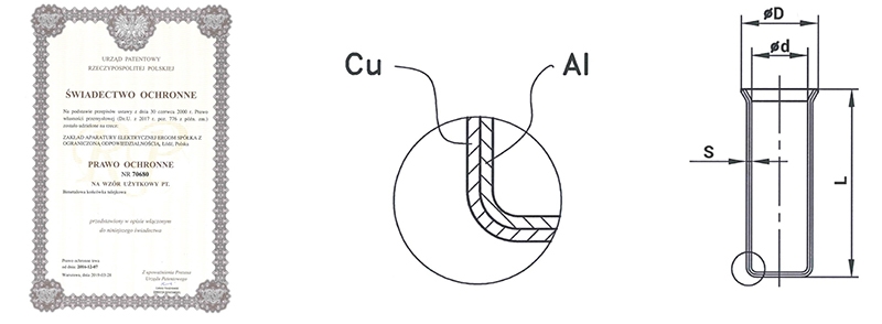
Fig. 3. Structure of the HMA type copper-aluminium cord end terminal.
In order to maintain compatibility between the copper cord end terminals and crimping tools already in use and the new bimetallic end terminals (HMA type), the same dimensions Ød and ØD have been retained. Slight differences in the L and S dimensions result from the manufacturing proces of the terminals and the mechanical parameters of the material used, Table 1.
| Cord end terminal type | L [mm] | Ød [mm] | ØD [mm] | S [mm] |
| HMA 6/12 | 12,5 | 3,5 | 4,7 | 0,25 |
| H 6/10 ERHN | 12,0 | 0,20 | ||
| HMA 10/12 | 12,5 | 4,5 | 5,8 | 0,25 |
| H 10/10 ERHN | 12,0 | 0,20 | ||
| HMA 16/12 | 12,5 | 6,0 | 7,5 | 0,25 |
| H 16/10 ERHN | 12,0 | 0,20 |
Table 1. Example comparison of the dimensions of H…ERHN and HMA tips.
HMA terminals are made from specially prepared bimetal sheets earlier wound on spools using cold plastic forming. Thanks to the appropriately selected number of pressings and pressure force, a high-quality and repeatable product is obtained without losing the characteristics of bimetal sheet, i.e. a permanent bond between two materials allowing for the optimal use of the properties of both metals.
The interior of the HMA terminals is additionally filled, before assembly on the cable core and crimping, with a certain amount of contact grease to improve conductivity and prevent air from entering the connection between the core and the inner part of the sleeve from the funnel-shaped extension. This prevents oxidation of the core. In addition, the grease, which also has abrasive properties, is designed to remove any aluminum oxides that may have formed during storage from the surface of the conductor and the inner part of the sleeve during crimping, Fig. 4.
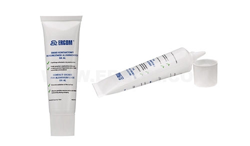
Fig. 4. SK-AL contact grease.
Comparative testing of sleeves
In order to verify the properties of the developed aluminium-copper cord end terminals (HMA type) comparative tests were carried out with copper end terminals of the same cross-section and crimped onto a conductor of the same cross-section. The tests used HMA 16/18 terminals crimped with a PZP 25/10-25/T tool with a single-notch crimping socket and H 16/18 ERHN terminals crimped with a PZP 16RL/6KT/0.08-16 tool with a hexagonal crimping socket. Both types of terminals were crimped onto wires with a nominal cross-section of 16 mm2. The tests covered the following parameters, which are most important from the point of view of terminal functionality:
- measurement of the cross-section smooth surface – after crimping the cord end terminal onto the cable conductor using a dedicated tool, it is cut and placed on a micrographic measurement station, where the quality of the crimp is assessed by determining the degree of filling of the terminals with the cable conductor onto which it was crimped. It is also possible to measure other characteristic parameters, such as terminal wall thickness, surface area, height and width of the crimped terminal, Fig. 5. The results of comparative measurements of crimped HMA and H...ERHN sleeves are presented in Table. 2. Applying contact grease to the inside of the terminal before crimping fills all free spaces, which will minimize aluminum oxidation and electrochemical corrosion. The test result is considered positive if the ratio of free space to total internal crimp area for the HMA terminal is not greater than the same ratio for the H...ERHN terminal crimped with the same tool.
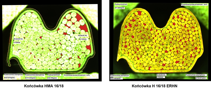
Fig. 5. Pictures of cut cord end terminals
| Cord end terminal type and crimping tool type | External surface area [mm2] | Inner surface [mm2] | Empty space area [mm2] | Percentage of empty space [%] | Cord end terminal wall thickness [mm] |
| HMA 16/18 PZP 25/10-25/T |
21.975 | 17.332 | 0.798 | 4,6 | Cu – 0.120 AL. – 0.125 |
| H 16/18 ERHN PZP 25/10-25/T |
21.460 | 18.051 | 1.689 | 9,4 | Cu – 0.183 |
Table 2. Results of comparative measurements of the cross-section smooth surface
- Pullout test – this test was performed based on the guidelines contained in section 9.2 of the UL486F standard, according to which H…ERHN cord end terminals are certified. Samples of appropriate length with cord end terminals crimped onto the conductor were mounted in the clamp of a static tensile testing machine and subjected to a tensile force of 100 N, in accordance with Table 8 of the above-mentioned standard, Fig. 6. The test result is considered positive if the wire is not pulled out of the crimped copper sleeve after applying the nominal force for 1 minute, Table 3. The deformations of the cord end terminals and pullout the core from the crimped copper sleeve, visible in the photos, are caused by applying a force exceeding the nominal value to determine its maximum value.
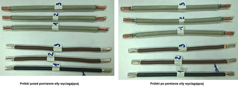
Fig. 6. Samples with tips before and after measuring the pulling force.
| Sample number | Al-Cu terminals crimped onto a class 5 aluminum wire with a cross-section of 16 mm2 | H…ERHN terminals crimped on a class 5 copper conductor with a cross-section of 16mm2 | ||||
| Required force [N] | Applied force [N] | Did the conductor protrude from the clamped cord end terminals after 1 minute [YES/NO]? | Required force [N] | Applied force [N] | Did the conductor protrude from the clamped cord end terminals after 1 minute [YES/NO]? | |
| 1 A-B | 100 | 101 | NO | 100 | 109 | NO |
| 2 A-B | 100 | 102 | NO | 100 | 103 | NO |
| 3 A-B | 100 | 101 | NO | 100 | 102 | NO |
Table 3. Results of comparative pull-out force measurements.
- Checking the voltage drop before and after the temperature increase test – this test was performed in accordance with the guidelines contained in section 7.2.4 of the PN-EN 60947-7 standard -1:2012P – the voltage drop at the clamp where the cable with the crimped cord end terminal is installed should not exceed the permissible value specified in the standard, i.e. 1.6 mV per clamp. The voltage drop is measured on five consecutive clamps at measuring points 15 mm from the end of the copper sleeve mounted in the clamp, Fig. 7. The resistance measurement was performed using a MEGGER DLRO10HD low resistance meter, which forces a current of 10A on a measurement range of 2.5mΩ. The results of the resistance and voltage drop measurements for both types of cord end terminals are summarised in Table 4 and Table 5.
The test result was positive because the voltage drop across the individual connectors was ≤1.6mV.
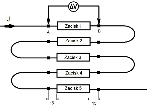
Fig. 7. Construction of the voltage drop measurement system.
| Measuring point | Al-Cu terminals crimped onto a class 5 aluminum wire with a cross-section of 16 mm2 | H…ERHN terminals crimped on a class 5 copper conductor with a cross-section of 16mm2 | ||||
| Current [A] | Measured resistance [µΩ] | Voltage drop [mV] | Current [A] | Measured resistance [µΩ] | Voltage drop [mV] | |
| 1 A-B | 9,82 | 119,3 | 1,17 | 9,82 | 74,8 | 0,73 |
| 2 A-B | 9,82 | 114,0 | 1,11 | 9,82 | 72,0 | 0,70 |
| 3 A-B | 9,82 | 121,3 | 1,19 | 9,82 | 71,9 | 0,70 |
| 4 A-B | 9,82 | 118,3 | 1,16 | 9,82 | 70,6 | 0,69 |
| 5 A-B | 9,82 | 113,7 | 1,11 | 9,82 | 74,4 | 0,73 |
| Resistance of the entire measuring circuit [mΩ] | 11,63 | 7,71 | ||||
Table 4. Results of resistance and voltage drop measurements before checking the temperature increase.
| Measuring point | Al-Cu terminals crimped onto a class 5 aluminum wire with a cross-section of 16 mm2 | H…ERHN terminals crimped on a class 5 copper conductor with a cross-section of 16mm2 | ||||
| Current [A] | Measured resistance [µΩ] | Voltage drop [mV] | Current [A] | Measured resistance [µΩ] | Voltage drop [mV] | |
| 1 A-B | 9,82 | 121,7 | 1,19 | 9,82 | 75,7 | 0,74 |
| 2 A-B | 9,82 | 117,6 | 1,15 | 9,82 | 71,1 | 0,69 |
| 3 A-B | 9,82 | 121,8 | 1,19 | 9,82 | 72,2 | 0,70 |
| 4 A-B | 9,82 | 120,6 | 1.18 | 9,82 | 69,7 | 0,68 |
| 4 A-B | 9,82 | 115,0 | 1,12 | 9,82 | 73,0 | 0,71 |
| Resistance of the entire measuring circuit [mΩ] | 12,23 | 7,7 | ||||
Table 5. Results of resistance and voltage drop measurements after checking the temperature increase.
- Checking the temperature increase – this test is performed based on the guidelines contained in section 7.2.1 of the PN-EN 60947-7-1:2012P standard – the temperature increase of the clamp in which the cable with a crimped cord end terminal is installed cannot exceed 50K above the ambient temperature at the rated current load for a given cross-section. The temperature increase is measured on five consecutive clamps by installing thermocouples in each of the crimped cord end terminals at both ends of the clamp at the connection point. The temperature is considered stable if it does not change by more than ±2K within 10 minutes, Fig. 8. The parameters of the temperature increase test were as follows: heating time t1 = 35 minutes, cooling time t2 = 25 minutes, steady-state current J = 75-78A.
The results of the temperature rise measurements for individual clamps are presented in Table 6.
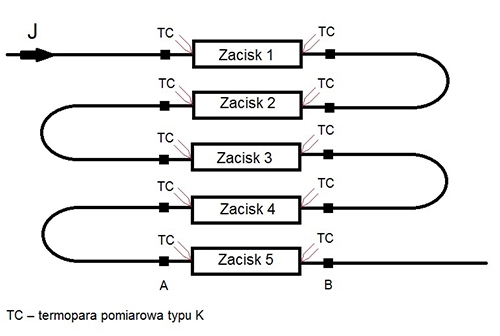
Fig. 8. Structure of the temperature rise measurement system.
| Measuring point | Al-Cu terminals crimped onto a class 5 aluminum wire with a cross-section of 16 mm2 | H…ERHN terminals crimped on a class 5 copper conductor with a cross-section of 16mm2 | ||
| Measured temperature [°C] | Temperature increase[°C] | Measured temperature [°C] | Temperature increase[°C] | |
| 1 A | 53,80 | 30,60 | 45,64 | 22,94 |
| 1 B | 53,70 | 30,50 | 44,22 | 21,52 |
| 2 A | 56,06 | 32,86 | 46,49 | 23,79 |
| 2 B | 55,58 | 32,38 | 45,55 | 22,85 |
| 3 A | 52,91 | 29,71 | 44,80 | 22,10 |
| 3 B | 55,01 | 31,81 | 46,33 | 23,63 |
| 4 A | 54,89 | 31,69 | 46,40 | 23,70 |
| 4 B | 52,47 | 29,27 | 45,12 | 22,42 |
| 5 A | 52,44 | 29,24 | 44,75 | 22,05 |
| 5 B | 50,68 | 27,48 | 42,01 | 19,31 |
| Room temperature [°C] | 23,20 | 22,70 | ||
Table 6. Temperature rise measurement results.
- Ageing tests – this test is performed after the temperature increase test based on the guidelines contained in section 8.4.7 of PN-EN 60947-7-1:2012P – clamps with wires fitted with crimped cord end terminals are subjected to 192 heating cycles in a climatic chamber (15 minutes at 40°C±5°C / 15 minutes at 30°C±5°C / humidity ≈ 50%). After every 24 cycles, voltage drops are checked, which should not exceed the permissible value in the standard, i.e. 4.8 mV per clamp or 1.5 times the value measured after 24 cycles. The voltage drop is measured on five consecutive clamps at measuring points 15 mm from the end of the sleeve mounted in the terminal. The forcing current flowing through the tested system is at least 10% of the forcing current value during the temperature rise test. This test was performed in the OBR ORAM research laboratory and its results before and after the test are presented in Table 7.
The test result was positive because the voltage drop across the individual connectors was ≤4.8 mV.
| Measuring point | Al-Cu terminals crimped onto a class 5 aluminum wire with a cross-section of 16 mm2 | H…ERHN terminals crimped on a class 5 copper conductor with a cross-section of 16mm2 | ||||
| Current [A] | Measured resistance [µΩ] | Voltage drop [mV] | Current [A] | Measured resistance [µΩ] | Voltage drop [mV] | |
| Measurement before the aging test | ||||||
| 1 A-B | 9,82 | 121,7 | 1,19 | 9,82 | 75,7 | 0,74 |
| 2 A-B | 9,82 | 117,6 | 1,15 | 9,82 | 71,1 | 0,69 |
| 3 A-B | 9,82 | 121,8 | 1,19 | 9,82 | 72,2 | 0,70 |
| 4 A-B | 9,82 | 120,6 | 1,18 | 9,82 | 69,7 | 0,68 |
| 5 A-B | 9,82 | 115,0 | 1,12 | 9,82 | 73,0 | 0,71 |
| Measurement after 192 cycles | ||||||
| 1 A-B | 9,65 | 120,2 | 1,18 | 9,65 | 74,3 | 0,73 |
| 2 A-B | 9,65 | 117,1 | 1,15 | 9,65 | 67,2 | 0,66 |
| 3 A-B | 9,65 | 114,1 | 1,12 | 9,65 | 70,3 | 0,69 |
| 4 A-B | 9,65 | 111,0 | 1,09 | 9,65 | 69,2 | 0,68 |
| 5 A-B | 9,65 | 114,1 | 1,12 | 9,65 | 72,3 | 0,71 |
Table 7. Results of resistance and voltage drop measurements after ageing test.
Application of HMA terminals in an industrial extension cord
The developed HMA terminal solution was verified by using a portable plug and a 63A portable socket, a five-core aluminum cable with class 5 conductors with a cross-section of 16mm², an industrial extension cord, and checking the temperature increases, Fig. 9.
HMA 16/18 terminals, after applying SK-AL contact grease to their interior, were crimped onto the aluminium conductors using a PZP 25/10-25/T tool with a single-notch crimping socket, Fig. 10. At one end, the cable was terminated with a portable socket and at the other end with a portable plug with a rated load of 63A. The extension cord thus made was connected to the same set of 63A industrial plug and socket, to which a five-core copper cable with class 5 cores with a cross-section of 16mm2 was connected, Fig. 11. The copper cable conductors were terminated with H 16/18 ERHN ferrules, which were crimped using a PZP 16RL/6KT/0.08-16 tool with a hexagonal crimping socket, Fig. 11.
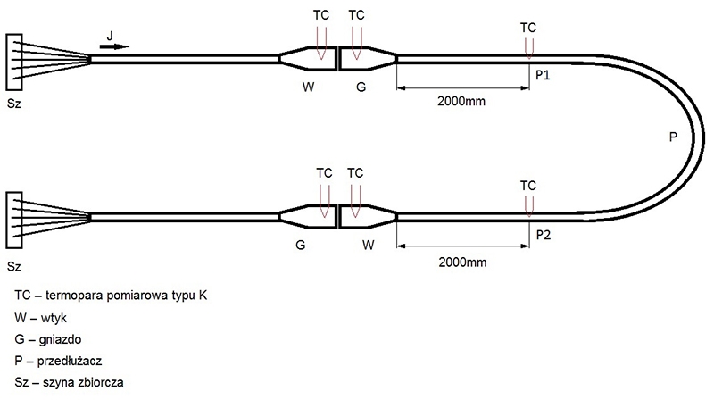
Fig. 9. Design of a system for measuring the temperature rise of an industrial extension cord.
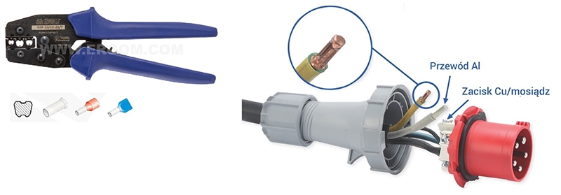
Fig. 10. Application of the HMA terminal in a 63A portable socket/plug
The temperature increase test was performed in accordance with the guidelines contained in section 22 of the PN-EN 60309-1:2002 – the temperature increase of the plug and socket in which a cable with an cord end terminal (HMA or H...ERHN type) clamped onto it is installed must not exceed 50K above the ambient temperature at the rated current for a given cross-section. In accordance with the requirements of the standard for equipment with a rated current of 32-125A, the continuous load time was 2 hours. The temperature is considered stable if it does not change by more than ±2K within 10 minutes. For the system shown in Fig. 11, the test parameters were as follows: heating time – 120 minutes, cooling time – 45 minutes, steady-state current – 62-64A, and the measurement results are presented in Table 8.
The test result was positive because the temperature increase above the ambient temperature measured on individual plugs/sockets was ≤50K.
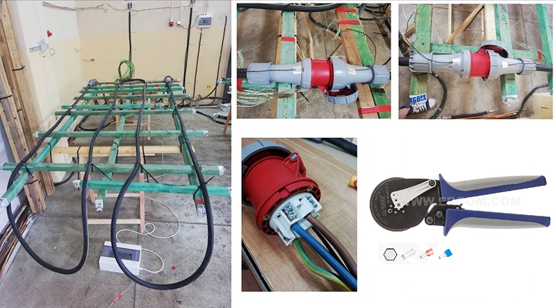
Fig. 11. Picture of the extension cord on the test bench.
| Measuring point | Al-Cu terminals crimped onto a class 5 aluminum wire with a cross-section of 16 mm2 | H…ERHN terminals crimped on a class 5 copper conductor with a cross-section of 16mm2 | |||
| Measured temperature [°C] | Temperature increase[°C] | Measured temperature [°C] | Temperature increase[°C] | ||
| Plug | power supply | 47,50 | 23,61 | 44,20 | 19,70 |
| extension cord | 50,35 | 26,46 | 43,71 | 19,21 | |
| socket | power supply | 46,78 | 22,89 | 43,29 | 18,79 |
| extension cord | 53,43 | 29,54 | 43,47 | 18,79 | |
| P1 cable | 60,42 | 36,53 | 49,71 | 25,21 | |
| P2 cable | 59,63 | 35,74 | 49,61 | 25,11 | |
| Tpom | 23,89 | 24,5 | |||
Table 8. Results of temperature increase measurements for a 63A industrial extension cord.
Conclusions
- Comparative tests of HMA 16/18 terminals crimped onto Al. 5 class conductors with H 16/18 ERHN terminals crimped onto Cu 5 class conductors showed that the proposed solution for terminating aluminium cable conductors fulfils its function both mechanically (measurement of the cross-section smooth surface, pull-out force measurement) as well as electrically (voltage drops, connection resistance). Due to its optimal electrical and mechanical parameters, the HMA terminal also achieves positive results in temperature increase tests.
- Offering the user a cord end terminal designed in accordance with the guidelines of DIN 46228/1 enables the safe connection of an aluminium conductor to a terminal made of copper or its alloys and does not require the construction of a new tool base.
- Temperature increase in industrial extension cords made with sockets, portable plugs, and cables with class 5 aluminium conductors terminated with cord end terminal (HMA type) are within the limits defined in the referenced standard. Tests have shown that with a properly designed terminal and the use of crimping technology, it is possible to ensure that the technical and operational requirements for extension cords with class 5 aluminium conductors are met.
- The manufacture of an extension cord with class 5 aluminium conductors makes it possible to reduce its weight and manufacturing costs while maintaining electrical parameters that are no worse than those of currently used extension cords with class 5 copper conductors.
Literature
1. Catalogue cards of the aluminium cable manufacturer, TFK
2. Catalogue cards of the copper cable manufacturer, ELEKTROKABEL
3. Catalogue cards of the manufacturer of 63A portable sockets/plugs, PCA
4. Catalogue cards of the manufacturer of single-track connectors, OUNEVA
5. https://www.dehn-international.com