KMA aluminium-copper cable lugs – guaranteed connection quality
Marcin Lis, Head of the ZAE ERGOM Laboratory
Daniel Mirowski, Head of the ZAE ERGOM Product Development Department
Michał Uciński, Product Engineer at ZAE ERGOM
In the power industry, cables with aluminium conductors terminated with aluminium cable lugs are used to transmit electricity between substations or between a substation and the end user. Unfortunately, such a connection cannot be directly screwed to a copper substrate, e.g. copper busbars or terminals of switchgear made of copper or its alloys.
The potential values of electrical copper and aluminium are different, Al.≈-1.66µV and Cu≈+0.53µV, which means that placing these metals adjacent to each other in a corrosive environment causes the metal with a more negative potential – aluminium – to corrode.
To avoid electrochemical corrosion at the contact point between copper and aluminum, and consequently an increase in the resistance of such a connection and its damage as a result of excessive temperature increase, one of two solutions should be used: coat the aluminium end with a layer of tin, whose normal potential is ≈ -0.14µV, or use a bimetallic (aluminium-copper) washer to ensure separation at the contact point.
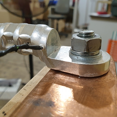
However, such solutions are not without their drawbacks. If the cable lug is coated with tin with a thickness of 3-5µm, any mechanical damage to this coating at the point of contact may initiate electrochemical corrosion. In the case of a bimetallic washer, an additional element is introduced into the connection (photo 1), which increases the resistance of the connection, resulting in a greater temperature increase of the cable lug under current load.
 |
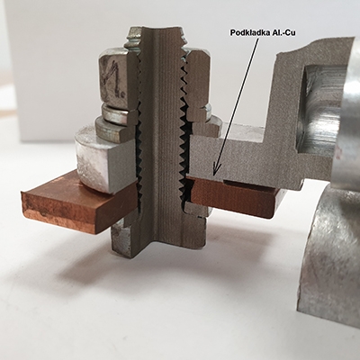 |
Photo 1. Aluminium cable lug connected using an Al-Cu washer
In addition, the entire connection, which operates in conditions conducive to the formation of water vapour condensation, should be protected with a special SW-LI lithium grease to prevent condensation from penetrating between the cable lug and the connection rail.
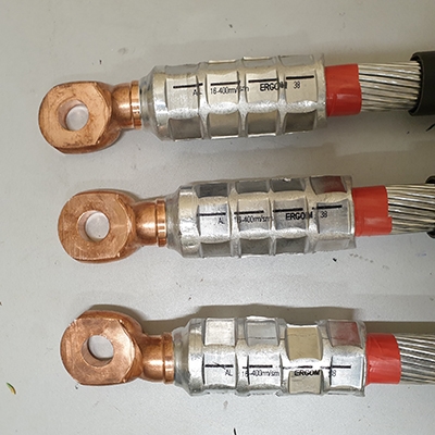
The ZAE Ergom Factory Laboratory conducted comparative tests of the KRA aluminium cable lug with a standardised Al-Cu washer and the KMA cable lug, which were connected to a copper busbar (photo 2).
 |
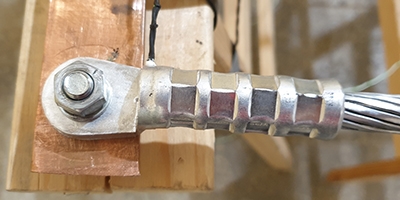 |
Photo 2. KMA aluminium-copper cable lug and KRA aluminium cable lug
The transition resistances between palm of the copper lug and the rail were compared, as well as the temperature increase of the lugs after loading them with the rated current for a given power cable cross-section on which the lugs were crimped. In addition, the lugs were crimped with different types of dies, i.e. a standard hexagonal die of the KP22… type and a hexagonal die with fangs of the KP22-MW… type on a class 2 YAKY 1x120 RMC cable core. The results of the comparative measurements are presented in Table 1.
| Tip type | Crimping die type | Current load for 120mm2 Al wire [A] | Steady state tip temperature [°C] | Transition resistance between fin and rail [µΩ] | Comments |
| KMA 120/10 | KP22-22 | 303 | 37,1 | 2,1 | - |
| KMA 120/10 | KP22-MW120 | 303 | 36,1 | 1,9 | - |
| KRA 120/10 | KP22-22 | 302 | 50,3 | 18,1 | Standardized Al-Cu washer |
| KRA 120/10 | KP22-MW120 | 302 | 46,7 | 13,4 | Standardized Al-Cu washer |
Table 1. Comparative tests of KRA cable lugs with Al-Cu washers and KMA cable lugs
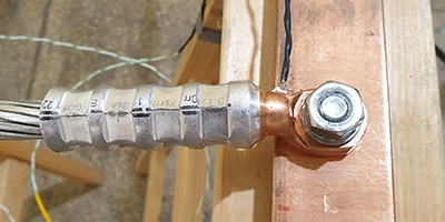
A solution that does not have the above-mentioned disadvantages are sealed aluminium-copper cable lugs of the KMA type (photo 3), which are designed for direct connection of cables with aluminium conductors to copper distribution busbars or equipment terminals made of copper or its alloys. It eliminates the need for a bimetallic washer in the connection and prevents electrochemical corrosion. Properly crimping the lug onto the conductor and securing the contact point between the lug and the cable insulation with a TGRK adhesive heat-shrink sleeve prevents oxidation of the aluminium conductor.
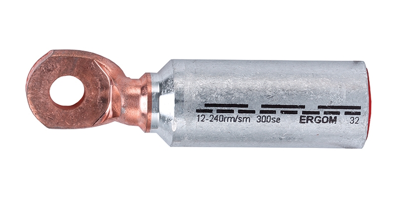
Photo 3. Picture of a KMA cable lug with a cross-section of 240 mm².
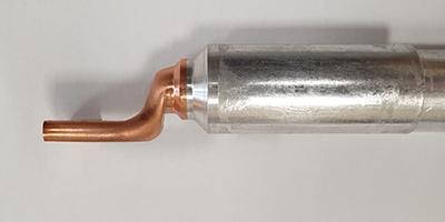
KMA cable lugs are made of an aluminium rod and a copper rod, which are joined together by automatic friction welding, ensuring a secure mechanical and electrical connection between these metals. The part is then subjected to further mechanical processing to obtain the correct dimensions of the copper part and the shape of the transition between the composite materials (picture 4). The correctly selected shape of the transition, its dimensions and the size of the connection palm guarantee optimal operating parameters of the power supply system.
 |
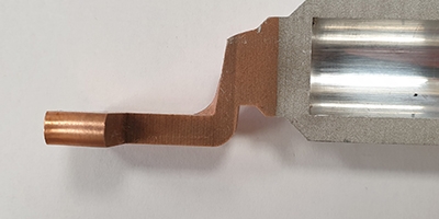 |
Photo 4. AL-Cu connection in the KMA cable lug
The diameters (internal and external) of the tubular part and its length comply with DIN 46239:1983-07. In addition, information on the surface of the tube section of the connector includes the crimping die socket number, the number and width of crimps, making it easier for the user to select the correct size of crimping die socket and to make a secure mechanical and electrical connection.
To completely prevent oxidation of the cable core, a small amount of SK-AL contact grease is applied inside the tubular part. This grease has abrasive properties and, during crimping, is designed to remove aluminium oxides formed on the cable core and the inner surface of the tubular part of the lug. These oxides have insulating properties and can increase the resistance of the connection, which in turn results in increased energy losses and a significant increase in the temperature of the connection. In addition, during crimping, this grease flows out and fills the empty spaces in the conductor, limiting air access to the interior of the lug and the cable conductor. The tubular part is sealed with a plastic plug that protects the interior of the lug from oxidation during storage.
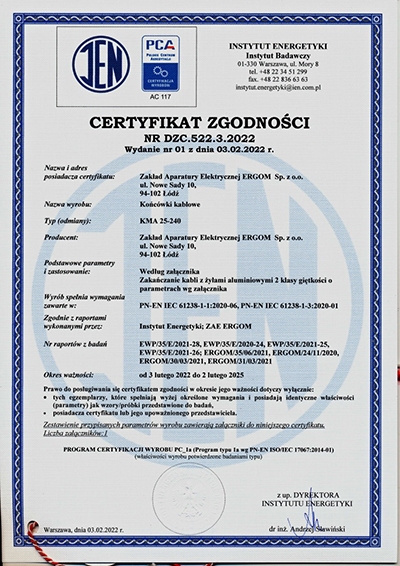
The mechanical and electrical properties of KMA cable lugs have been confirmed during lug testing conducted at the Institute of Power Engineering in Warsaw and at the ZAE ERGOM Plant Laboratory. Obtaining a certificate of compliance with the standard PN-EN IEC 61238-1-3:2020-01 and PN-EN IEC 61238-1-1:2020-06 for electrical class A – with short-circuit test and mechanical class 1 allows for the safe use of the lug in the power system (picture 5).
 |
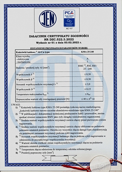 |
Photo 5. Certificate of conformity for KMA cable lugs up to 240 mm².
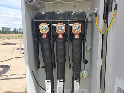
The operational and technical advantages of KMA cable lugs, i.e. the high quality of the aluminium and copper connection, have already been appreciated by companies operating in the renewable energy sector, e.g. in photovoltaic farms for connecting inverters in individual PV cell chains to fuse disconnectors in transformer substations (picture 6).
 |
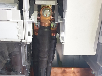 |
Photo 6. Example of KMA cable lugs used in a photovoltaic farm.
To meet customer expectations and the needs of renewable energy markets, we have begun the process of certifying KMA cable lugs with a cross-section of 400 mm² for compliance with the following standards:
• PN-EN IEC 61238-1-3:2020-06 (cable lugs for applications with a rated voltage of up to 1kV);
• PN-EN IEC 61238-1-3:2020-01 (cable lugs for applications with a rated voltage of 1kV to 36kV).
Mechanical tests (pullout test) of KMA 400/16 cable lugs (3 samples) crimped with a HH-630 hydraulic head using a 15 mm wide AH6-38 crimping die showed that the proposed number of crimps, their width and the size of the die are optimal for this type and cross-section of cable lugs (picture 7).
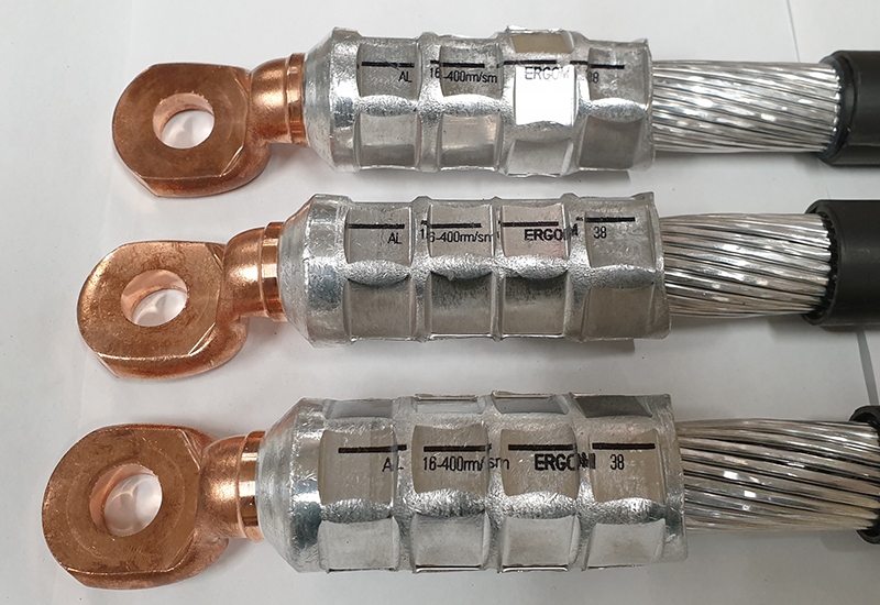
Photo 7. Pictures of samples before pullout test.
Samples of appropriate length were mounted in the clamp of a ZDM-5 static tensile testing machine and subjected to tensile testing with a nominal force of 16,000 N. The test result is considered positive if, after applying the nominal force for 1 minute, the cable core is not pulled out of the clamped end by more than 3 mm. The deformations and damage to the cable lugs (picture 8) are caused by the application of a force significantly exceeding the nominal value to determine the maximum mechanical strength of the cable lug. The measurement results are presented in Table 2.
 |
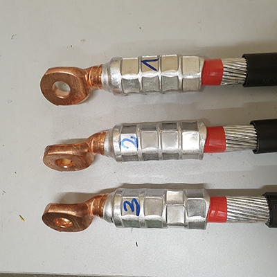 |
Photo 8. Pictures of samples after mechanical tensile strength testing.
| Sample number | Force required according to standard [N] | Force applied within 1 minute. [N] | Did the conductor protrude from the clamped cable lug after 1 minute [YES/NO]? | Maximum applied force causing tip damage [N] |
| 1 | 1600 | 16200 | NO | 23800 |
| 2 | 1600 | 16250 | NO | 23450 |
| 3 | 1600 | 16300 | NO | 23400 |
Table 2. Results of mechanical strength measurements of the lug.
Mechanical tests confirm the very high quality of the copper and aluminum bond. Mechanical damage to the cable lug after applying the maximum tensile force does not occur at the bond point, ensuring that the terminal maintains its mechanical properties in the event of a short circuit.
Literature
- PN-EN IEC 61238-1-3:2020-01 – Clamped and screw connectors for power cables -- Part 1-3: Test methods and requirements for crimped and screw connectors for power cables with a rated voltage higher than 1 kV (Um = 1.2 kV) up to 36 kV (Um = 42 kV) tested on insulated cores.
- PN-EN IEC 61238-1-1:2020-06 – Compression and screw connectors for power cables -- Part 1-1: Test methods and requirements for compression and screw connectors for power cables with a rated voltage up to 1 kV (Um = 1.2 kV) tested on insulated cores.
- DIN 46329:1983-07 – Cable lugs for compression connections, ring type, for aluminium conductors.